Milestone 1: Line Follower
Our goal for milestone 1 was to have our robot autonomously follow a line in a figure-8 pattern. To implement this ability, we started off by deciding the arrangement of the line sensors to recognize a straight path along a piece of black tape on a white background. After achieving this functionality, we developed our code to enable the robot to traverse a grid of lines and follow a figure-8 pattern.
Part 1: Line Detection
For our robot to detect and follow a simple, straight line, we first tested the QRE1113 line sensors to see what values corresponded with light and dark surfaces. With those values, we decided to place two line sensors in the center, spaced apart with a distance slightly greater than the width of the line. Using two sensors instead of four guaranteed that there would be sufficient analog pins. With this design, the two values from the sensors provide information on which way to adjust heading.
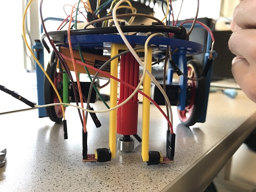
Figure 1. Placement of line sensors on robot. (Front View)
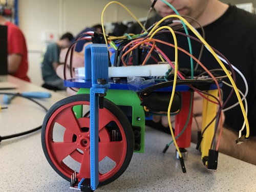
Figure 2. Placement of line sensors on robot. (Side View)
Now we determine under what conditions should each servo move or stop. Here’s the logic we used:
If both the left sensor and right sensor detect the black line (i.e. the sensor outputs a value greater than a pre-determined threshold which indicates a dark surface), robot is perpendicular to the line and needs to turn in one direction.
If left sensor is on the line and right sensor is not, robot drifted right and needs to turn slightly left.
If right sensor is on the line and left sensor is not, robot drifted left and needs to turn slightly right.
If both sensors detect light (are not on the line), then the robot is centered on the line, provided that the robot has been following a line. If the robot is no longer on a line, it will think it’s centered and will keep going straight.
Link to a short video of our robot following a straight line: Video
Another video of our line-following robot, this time following a curve: Video
Our robot appears slower in the second video due to the curvature of the line. We will not have to worry about following a curved line while traversing the maze, however, so our robot will be able to move faster.
Part 2: Autonomous Figure-8 Movement
The next part of our milestone 1 involved turning and detecting intersections in a grid to produce a figure 8. An intersection was detected when both light sensors were on a line, indicating that the robot should turn 90 degrees right or left, where direction is determined by a coded figure 8 sequence. To move the robot in a figure-8 pattern, the code keeps track of the direction the robot should turn (x = 1 indicates right turn, x = 0 indicates left turn) and the number of consecutive turns in that direction (variable y). For example, if x = 0, and y = 1, the robot would turn left at an intersection and would keep turning left at intersections while incrementing y by 1, y++, until the number of consecutive left turns completed is 4, y>4. At that point, y is greater than 4, so the robot would change its turn direction (x = 0), would restart its tracking of consecutive turns (y = 1), and turn right four times, y++ per a turn until y>4. This produces a figure 8 pattern and repeats in an infinite loop.
Here’s a link for video of our robot’s autonomous figure-8 movement: Video
Below is a commented version of the code used:
#include <Servo.h>
int QRE1113_PinL = 0; // connect left light sensor to analog pin 0
int QRE1113_PinR = 1; // connect left light sensor to analog pin 1
int onLine = 850;     // threshold value for sensor on line
int onStatL;          // returns boolean for statment "left sensor is on the line"
int onStatR;          // returns boolean for statment "right sensor is on the line"

int val = 100;        //normal motor speed
int offVal = 140;     //motor speed when sensor is off line, faster to correct
Servo left;           //set up left and right motor
Servo right;
int x=0;              // Determines turn direction in binary
int y=1;              // Keeps track of number of turns

void setup() {
  Serial.begin(9600);
  left.attach(5);    // connect left servo to pin 5
  right.attach(3);   // connect right servo to pin 3
}

void loop() {
  //determine whether robot is on the line
   int QRE_ValueL = analogRead(QRE1113_PinL); //measure light value for left sensor
   int QRE_ValueR = analogRead(QRE1113_PinR); // measure light value for right sensor

  //determine line status for left sensor
   if (QRE_ValueL > onLine) onStatL = 1;
   else onStatL = 0;

   //determine line status for right sensor
   if (QRE_ValueR > onLine) onStatR = 1;
   else onStatR = 0;

  //drive servos
   // if both sensors on either side of line, the robot is centered
   if(!onStatL && !onStatR){
    // continue traveling straight
    // Note that servos rotate in opposite direction, 90 is 0rpm,
    // so values 100 to left servo and 80 to right servo cause forward motion
    left.write(100);
    right.write(80);
    Serial.println("Centered");
   }

    // if left sensor is on the line, and right sensor is off the line, the robot drifted right
   else if(onStatL && !onStatR){
    // put left wheel to 0rpm and rotate right wheel forward to turn robot left to straighten heading
    left.write(90);
    right.write(80);
    Serial.println("Robot drifted right");
   }

    // if left sensor is off the line, and right sensor is on the line, the robot drifted left
   else if(!onStatL && onStatR){
   // put right wheel to 0rpm and rotate left wheel forward to turn robot right to straighten heading
    left.write(100);
    right.write(90);
    Serial.println("Robot drifted left");
   }

  // if both sensors are on the lines, an intersection is reached
    else if((onStatL) && (onStatR)){
    // when x becomes 1, the robot turns right at intersections four times
      if (x) {
        left.write(90);
        right.write(80);
        y++; // y increments at each turn
        if (y>4) { // this changes the turning direction and resets y
          x=0;
          y=1;
        }
        Serial.println("Turn 90 Degrees Right");
        delay(1000); // 1000ms turning time is approximately 90 degrees
      }
      // when x becomes 0, the robot turns left at intersections four times
      else {
        left.write(100);
        right.write(90);
        y++; // y increments at each turn
        if (y>4) { // this changes the turning direction and resets y
          x=1;
          y=1;
        }
        Serial.println("Turn 90 Degrees Left");
        delay(1000); // 1000ms turning time is approximately 90 degree
      }

  }

    // this case cannot be reached unless some software glitch occurred. In that case, the robot would spin in circles
  else{
     left.write(100);
     right.write(100);
  }

   Serial.print("\n");
   delay(2); // check the status of sensors every 2ms + time it takes this code in loop to run

}